- makeITcircular 2024 content launched – Part of Maker Faire Rome 2024Posted 1 month ago
- Application For Maker Faire Rome 2024: Deadline June 20thPosted 3 months ago
- Building a 3D Digital Clock with ArduinoPosted 8 months ago
- Creating a controller for Minecraft with realistic body movements using ArduinoPosted 8 months ago
- Snowflake with ArduinoPosted 9 months ago
- Holographic Christmas TreePosted 9 months ago
- Segstick: Build Your Own Self-Balancing Vehicle in Just 2 Days with ArduinoPosted 9 months ago
- ZSWatch: An Open-Source Smartwatch Project Based on the Zephyr Operating SystemPosted 10 months ago
- What is IoT and which devices to usePosted 10 months ago
- Maker Faire Rome Unveils Thrilling “Padel Smash Future” Pavilion for Sports EnthusiastsPosted 11 months ago
3Dprint your halloween special with 3Drag
The night of the witches is coming: we need thus to gear up with a suitable decoration, so to create an atmosphere worthy of this celebration.
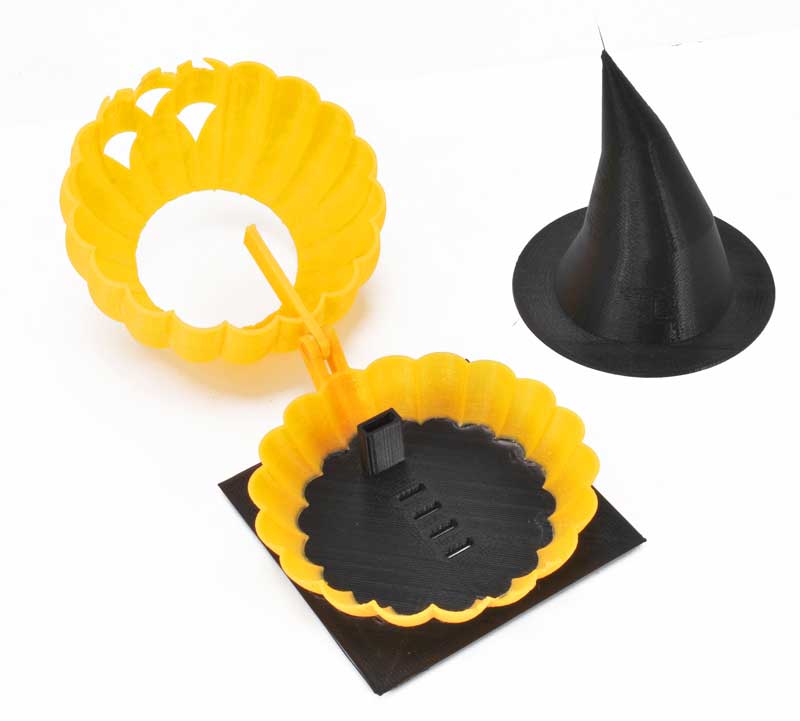
For this circumstance there are many suggestions on the Internet, and specially creations made with 3D printers; among those available on the popular website Thingiverse, we chose a “dynamic” decoration, that is to say a pumpkin that automatically opens and closes its mouth. Inside of it there are some ghosts that move over and over again (the item is number 506863, created by gzumwalt).

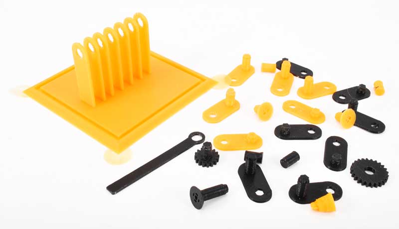
All the parts composing the item have been printed by our wonderful 3Drag, and have been properly assembled.


…and so on.

Immediately, the idea of integrating the item with some electronic circuits jumped to our minds: to enable the activation of the movement, when a person is passing by: this would give our 3Dprinted Halloween pumpkin an even more “spectral” appearance!
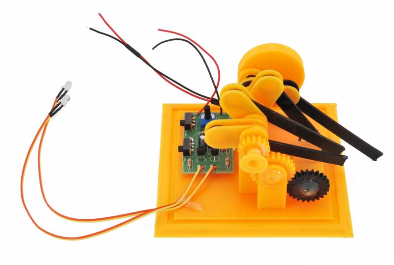
The first objective – presence sensitivity – has been reached by using a simple PIR module (Open electronic’s code: MINIPIRMOD)
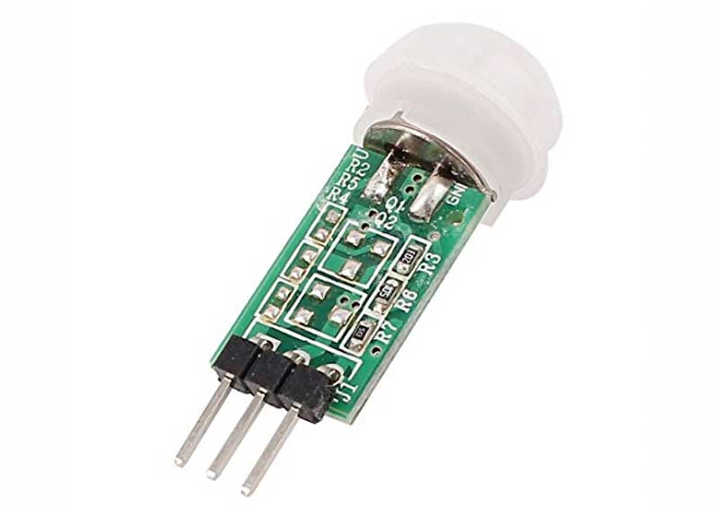
By means of a 4K7 ohm resistor, a Darlington MPSA13 transistor has been connected at its output: the transistor controls an ultraminiature 5Vdc relay, needed in order to supply the power source (or to take it away) to the micro gearmotor (Futura Elettronica’s code: MMG150) and to the stroboscope installed inside the item. The activation of the relay is signalled by a green 3 mm LED, connected in parallel to the relay wiring by means of a 120 ohm resistor, as it can be seen from the circuit diagram below.

The components we just mentioned, along with a pair of terminals, have been welded on a practical matrix board, that is more than adequate for this purpose.
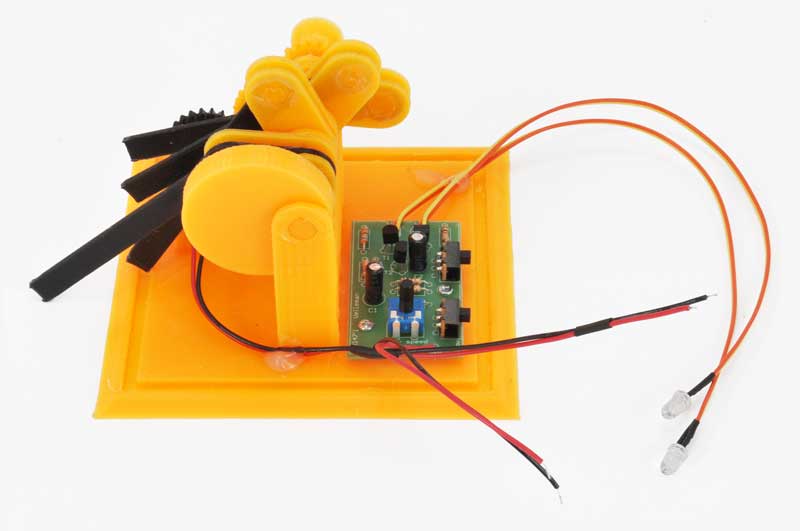
In order to make the decoration look even better, we installed 2 high brightness white LEDs inside the pumpkin’s mouth. They are controlled by an electronic circuit (available for sale in a kit – Futura Elettronica’s code: MK147) that enables the realization of an incisive stroboscopic effect.
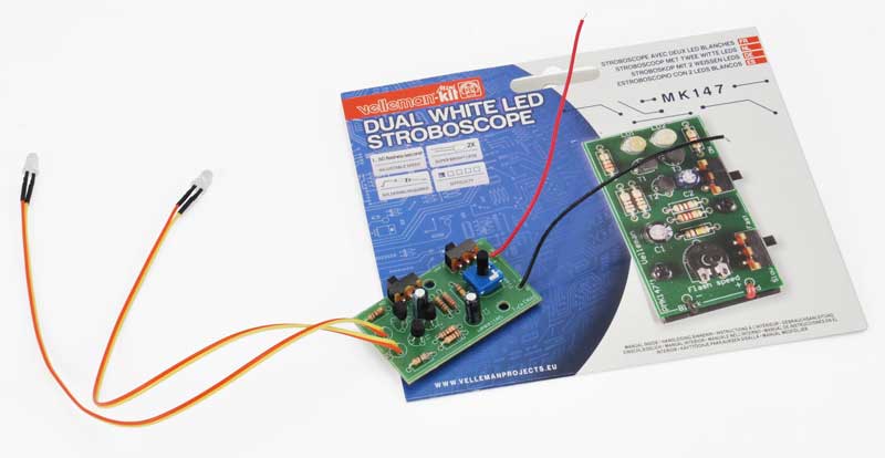
Since everything was powered by means of a voltage of just 5Vdc, in order to make the motor turn much slower we had to modify the original configuration of the 2 LEDs (that expected a serial connection), so to guarantee the same light emission that we would obtain via the power voltage considered by the circuit (9Vdc). Substantially, the LEDs have been removed from the board and connected in parallel to the same board, in the points A and B (as it can be seen from the diagram below) by means of two 68 ohm 1/4W (R8, R9) resistors and two twisted pair wirings (so to install them in the pumpkin’s mouth), while the R7 resistor, found on the PCB, has been shortcircuited by means of a jumper (JP1).


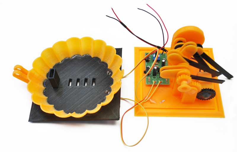
The RV1 trimmer has been regulated in order to achieve the desired stroboscopic effect. In the back panel, at the base of the item, a 8 mm hole has been made in order to secure the DC socket, while in the front panel a 12,5 mm hole has been made, in order to insert the PIR sensor’s lens. The two boards, on the other hand, have been installed inside the box (the matrix board is behind the sensor, while the MK147 is on the base) and they have been fastened by means of a pair of self-tapping screws.

The motor has been secured in his housing, by means of some hot glue, and the same goes for the gear wheel, mounted on the corresponding pivot: this has been made in order to avoid movements along the axis, during the operations.
In the inferior part of the pumpkin’s mouth, two oblique 6 mm holes have been made, so to insert the 2 LEDs, then secured by means of the hot glue.
The motor and the MK147 have been connected to the + and – terminals, that respectively depend on the relay’s COMUNE and NA contacts, while the DC socket has been connected from the panel to the matrix board’s power terminals (PWR).
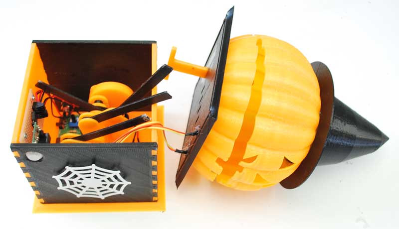


After the small command rods have been inserted in the corresponding holes, the spectral pictures have been applied.

By supplying 5V power to the DC socket, the pumpkin comes alive: it is now ready to make our Halloween celebration even more unique and magic!
From openstore
Micro Metal Gearmotor – 85 RPM

Related Posts


-
 Arduino ISP (In System Programming) and stand-alone circuits
We use an Arduino to program other ATmega without...
- Posted 12 years ago
-

-

-
 GSM GPS shield for Arduino
Shield for Arduino designed and based on the module...
- Posted 12 years ago
-
 Small Breakout for SIM900 GSM Module
Some post ago we presented a PCB to mount...
- Posted 13 years ago
-
 makeITcircular 2024 content launched – Part of Maker Faire Rome 2024
Applications to MakeITcircular must be in by October 3,...
- Posted 1 month ago
-
 SONY color camera module, 700 TV Lines
Color camera module equipped with a 1/3″ CCD sensor...
- Posted 2 months ago
-
 ESP32 Low Power Module
ESP32 Low Power Module, based on Espressif’s SoC capable...
- Posted 3 months ago
-

-
 Application For Maker Faire Rome 2024: Deadline June 20th
Learn More About the Ideas, Makers + Projects at...
- Posted 3 months ago